When I designed the table to hold my mixer, I added a pair of sloped racks on either side for rackmount gear. My thinking was that I’d put the gear that I’d use for tracking on the left, and the mixdown gear on the right, so that’s pretty much what I did.
But after a time, it became obvious that this wasn’t the best solution for several reasons. For one, having the equipment relatively low down means a lot of bending over to make adjustments and monitor what the gear is doing… not so ergonomically friendly. I also discovered that I need to have patch points near the interfaces, so I can change the signal routing into and out of the mixer and interfaces. Keeping the interfaces and preamps on the left seems to be ok, but for mixing, I needed a better solution… something at eye level and close to the patchbays, so that cable runs could be kept short.
I decided that I needed another rack. But this one should have casters so I could move it around… and roll it out of the way when I don’t need it. It’ll be taller so I can have some of my gear at eye level.
It will have a similar look to my existing racks, though, so it won’t look out of place. The lower section is slightly angled, while the top section is straight. I did some scribbling on the back of an envelope and came up with a design, and then ran to Home Depot. Here’s a rough cost breakdown:
- 1 sheet of 3/4″ birch plywood- $48
- 1 8′ length of 4″ white pine for the rails- $6
- a box of 1 5/8″ drywall screws- $6
- Lag screws for casters- $2.50
A set of 5″ casters, 2 swivel and 2 straight, $8 from a local discount industrial supply.
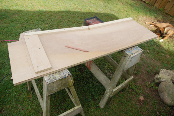
To start, I had the nice folks at the Depot make a couple cuts with their panel saw. This is a huge time saver, and the cuts are always accurate and square. The sides are 20″ wide by 48″ long, and I had them just split the remainder in two pieces so I could get it home easier.
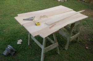
The panels were laid out back-to-back to increase accuracy.
Once at home, the sides were cut with a circular saw. I clamped the two panels together so the sides would be identical, and made some cuts to make the angled bottom half of the rack and the little notch at the bottom. I cleaned up these cuts with a saber saw and a sander, and then laid the two pieces out side by side on the sawhorses, opened up like a book. This way I would be sure to mark and screw in pieces to the inside face of the rack.

One of the sides with the blocks screwed into place
Since this rack was going to have casters, I decided it would be easier to have a flat bottom that the casters could screw to. But this flat bottom would be holding a lot of weight, so I added two blocks of plywood to the insides to help take the weight of the rack. They were screwed and glued into place. The wooden “rails” that the equipment screws in to were mounted on the sides, but these were mounted with screws only, since I could envision a time when these pieces would get replaced if/when the mounting holes get chewed up.
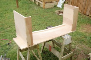
Using L-shaped top and bottom panels means that it’s easier to screw them to the sides.
After the side panels were ready, the top and bottom panels were built up. The inside space of the rack is 19 1/8″ wide, so I needed a piece for the bottom (20 x 19 1/8″), a piece for the top (16 x 19 1/8) and two small pieces to reinforce the back (4″ x 19 1/8″) I screwed and glued the small reinforcing pieces to the to and bottom panels. If they’re cut accurately, the rack will be square when you add these pieces. But if you’re not careful and these pieces are misaligned, the whole thing will be crooked. Since the top and bottom panels were now “L” shaped, the panels are a lot easier to screw into the sides without falling over.
Once this was done, it’s a fairly small matter to add on the other side. You’ll want to use screws and glue for these joints, since the rack will be supporting a lot of weight and the gear inside is rather expensive. A weak or wobbly rack just won’t do here. I wouldn’t use cheap plywood, either… use the good stuff. I had some 2″ screws left over from another project, and that’s what I used to secure the top and bottom.

Cutting a square hole with radiused corners is easy… just drill four holes with a spade drill and cut along the edges with a saber saw.
With the other side mounted in place, all that’s left is detail work. I made a cutout in the back for a power switch by drilling four holes with a spade drill, and sawing out the waste with a saber saw.
I didn’t mount the bottom panel on the very bottom of the rack, though. The bottom panel is raised about four inches from the bottom edge of the rack so the large, rather ugly casters are partially hidden. They are exposed in the front, though, so it isn’t a perfect solution.
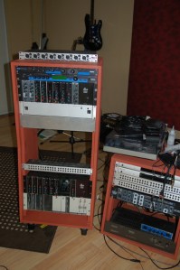
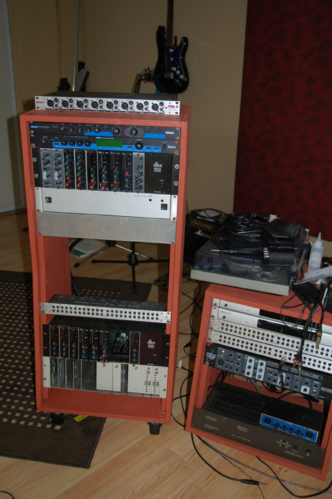
My completed rack with some of the equipment installed. The two blank panels below the 900 rack are for a pair of Universal Audio 1176 compressors that I’m building.
I had the rack assembled by lunchtime. In the afternoon, I filled the screw holes with drywall compound, sanded the sharp edges, and slapped on a coat of latex paint. The casters were screwed to the bottom, and that’s it… one new equipment rack.
Well, almost. I still need to mount a power switch to the back and screw a surge protector to the side of the rack. Yet another improvement that I’ve yet to finish is a small light to go on the inside of the rack. It’s extremely irritating to try to trace wiring in the back of a rack while you hold a flashlight in your teeth because you need both hands to hold the wiring. I’m still looking for a simple, small, low-wattage lighting solution for the back of my rack that doesn’t cost an arm and a leg.


ST9!~~60_57")


You must be logged in to post a comment.