Making audio cables is one of those things that I do without really thinking… I’ve made cables for so many years that it’s become second nature. It’s drop-dead easy as well… every audio person should make their own cables unless you’re just plain swamped with jobs. Not only will your finished cables be less expensive, but with care they’ll be higher quality than most of the cables that you’ll buy. All you need are a few tools, some QUALITY components, some time, and a place to work. (Exception- Hirose connectors or mini XLR types (TA-3, TA4, or Lectro mic input TA-5 types) are NOT easy to solder. I’ve done it, so it is possible, but you certainly don’t want to try these if you’re just starting out. I use a stereo dissection microscope when working with these kinds of connectors.)
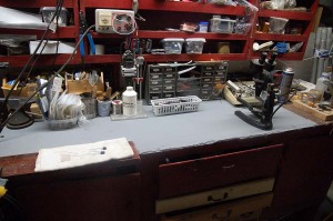
My electronics bench in the basement. I get into all sorts of trouble here. It’s good to have an assortment of tools and supplies within easy reach.
TOOLS
- A soldering iron (NOT a soldering gun). I have a Weller 25w and a 35w. The 35w has a little extra heat and power to melt solder on larger, heavier terminals, but I generally prefer my 25w with a fine conical tip. Smaller connectors, such as 3.5mm stereo jacks or the tiny Hirose require an iron with the finest tip you can get. Avoid cheap soldering irons… they are slow to heat and can damage semiconductors.
- Wire strippers. These range from simple and cheap (4-5 bucks) to automatic wire strippers (about 25 bucks). I always went the cheapskate route, until I finally bought a good, US-made pair of automatic strippers about a year ago. I should’ve bought these from the get-go… they work very well, and are much faster and easier than the cheap methods. For the truly frugal, you can use an Xacto knife, but be careful not to nick the conductors. Some wires are too fine for the auto strippers, so a knife isn’t a bad idea anyway.
- Wire cutters. I have several sizes and styles. My favorites, though, are my Xuron flush-cutters, for small wires only. (Again, these are US-made… are we starting to see a pattern here?) Large shielded cables require standard-size wire cutters.
- A heat source. A candle can work, but I finally bought a proper heat gun for shrinking heat-shrink tubing. Smoke from the candle sometimes leaves soot marks on your cables, which looks dirty.
- DVM or analog voltage meter for checking the circuits. An analog meter works fine, but the digital units are generally more capable. A cheap Chinese meter can be bought from Harbor Freight on sale for under five dollars these days, and will work for checking solder joints or batteries. If you spend some money for a good meter, though, these can measure all kinds of things, like inductance, capacitance, temperature, frequency. Try to get one with an auto shutoff feature. A real Fluke meter is on my wish list.
- Other tools are sometimes required, but not essential for every job. I have an assortment of tweezers, including the locking type for soldering- handy, especially for smaller connectors. I also have a rack of jeweler’s pliers that I reach for often.
CONSUMEABLES
- Quality audio cable. This is NOT the area to hunt for bargains. I use only cable by Canare or Mogami. Belden is an old standard. Good cable is expensive for a reason. It is completely pointless to do all this work if you can’t trust the cable itself, so get the real deal.
- Connectors. I prefer Neutrik over the old Switchcraft types, but both are quality products. Neutrik cables have a different strain relief design and can be disassembled in the field without tools, which is important for troubleshooting connection problems. The newer Switchcraft connectors have been redesigned and may make the differences less pronounced. But definitely stay away from anything selling direct from overseas on eBay.
- Solder. I purchased a large spool of fine rosin-core solder when my 20-year old spool from Radio Shack finally started looking thin. 60/40 solder containing lead is getting difficult to find, so buy some while you can. The flux is the key, buy solder from a reputable electronics supplier and you’ll be fine. But AVOID lead-free solder until you’re an expert… it may be better for the environment, but it’s much more difficult to solder than 60/40.
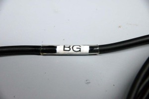
- Heatshrink tubing. Here’s the detail that will make your cables last longer than most ready-made cables. Adding a length or two of heatshrink takes a few minutes, but it distributes the strain of the cable better and protects the soldered joints. The cable shouldn’t move when you hold the connector still- add heatshrink until the cable matches the size of the hole in the connector shell. You can even take the extra step and add another layer of heatshrink outside of the connector shell, but this makes repairs more difficult. Another heatshrink trick is to buy a length of clear tubing. Label your cables with your name, then cover the label with a piece of clear for a permanent ID. Don’t use electrical tape on your connectors… it never lasts very long, and leaves a sticky residue when you remove it in order to do the job properly. Sometimes heatshrink is impossible to fit and you may have to use it to insulate something, but when I do I always finish it with a layer of heat shrink.
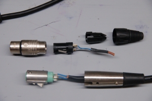
Neutrik vs. Switchcraft audio connectors. I prefer the Neutrik because the connector can be disassembled in the field without tools. Switchcraft connectors require a special tiny flathead screwdriver- we called them “tweakers” at the television station. Tweakers tend to dissappear when they’re needed most.
PROCEDURE/TECHNIQUE/STANDARDS
Actually building your cables is fairly simple. First, cut the cable to length. Because I have forgotten to do it SO many times, my next step is always to insert the screw-on connector shells. I’ll put on both ends facing back-to-back. Even though you don’t need to do this until after you’ve soldered your first cable end, I promise you that someday, somewhere, you’ll forget to add a shell and will have to cut off and re-solder a connector. Hopefully no one will be around to witness your dumb mistake, but I would challenge anyone who has built more than five cables who says they’ve NEVER forgotten a shell.
Add your label and clear heatshrink to ID the cable as yours. Strip the ends, leaving the leads fairly short, around a half inch. This ensures that the little plastic clutch will squeeze the outer shield, making your cable durable. (I’m assuming Neutrik connectors, Switchcraft may be different.) If you leave the leads too long, the plastic clutch will be totally ineffective, your soldered joints will stress from movement, and your cable will fail in a fairly short time. Build up the area that the clutch grabs with a length of heatshrink, about two inches should do it.
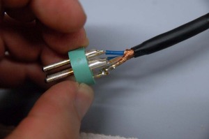
Now strip the individual leads and twist the strands. It sometimes makes life a little easier if you heat and tin the bare ends with a tiny spot of solder before you attempt to solder the connector, this prevents flyaway strands that could potentially cause a short. Not absolutely essential, though, if you’re careful, but it does make things easier later.
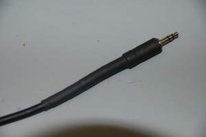
Smaller connectors like this 3.5mm stereo jack can benefit from a length of heatshrink over the entire connector, but this makes field repairs pretty much impossible. Not many folks have time to repair cables in the field, though. I always keep a minimum of two cables of every type that I use on set.
Pin 1 is the cable shield. Always. No exceptions. Well, maybe one…except when you’re wiring a “Starquad” or four-conductor cable, see below. If you are using standard audio cable with two conductors and a shield, then pin 1 is always connected to the shield. Pin two and three are for the signal positive and signal negative. This won’t matter when building the cable as long as the same wire goes to the same pin on each end. If you aren’t careful and solder pin 2 on one end to pin 3 on the other, then you’ve built a phase-reversing cable. If you use this cable alone with a single mic, no problem. But you’ll hear some weird effects if a mis-wired cable is used in a stereo pair.
Should you tie the connector shells?
On your connector you will notice a fourth lug. This is to provide an electrical connection to the outside of the shell of the connector. You will often see commercially-made cables made with this lug soldered to pin 1. This way, the shield of the audio cable is electrically connected to the metal case of the gear, which is grounded through the power outlet to the real earth somewhere. Hopefully. The trouble starts when you have a piece of gear that’s faulty, and some of the power supply voltage is being drained off by the case. Or… and this has happened to me once… you have a power outlet that’s incorrectly wired, and the ground at one outlet is a different potential from the ground of another… and both outlets are used in your signal chain. (I learned this the very hard way. saw a 1/4″ spark jump tp pin 1 when I went to plug in my audio cable… “What the FUç&?!…” while several people stood by me wondering when their $20,000 satellite shot was going to have sound.) There is a host of possible scenarios regarding grounding of audio equipment, and the best explanation I’ve found is by Rane called Grounding and Shielding Audio Devices. It tells you more than you wanted to know about grounding. But even more essential to the cable builder is Rane’s Note 110, Sound system interconnection. Read this before you build any cables… it covers all sorts of different cable types and ends, and tells you exactly how you should wire, say, a cable with a female XLR on one end and an unbalanced RCA at the other.
“Starquad” Cables
There is one cable type that isn’t mentioned in Rane 110, and that’s “Starquad” or “Neglex” cables. These cable types have four conductors surrounded by a shield, rather than the usual two, though only three conductors are used for balanced cables. To wire a Starquad cable, pins 1, 2, and 3 are connected to an inner conductor. The shield is connected to the cable shell at the male end only, with the shield and extra conductor cut short at the female end.
The advantage of this type of cable is the audio ground is kept separate from the chassis ground. The chassis ground is used to surround the audio conductors, protecting them from EMI (Electro Magnetic Interference). I’ve built a few of these and they work well.

Can you make a right angle 90° toslink to mini plug 3.5mm digital optical optic cable? I attempted to attached a couple of pics not able to copy/paste here. I’m pairing a sony d50 with sound devices usbpre 2 . SD line output(opt.) into the d50 3.5m line in input(opt.). If so how much would it cost ?
I’ve looked everywhere and just can’t seem to find a complete cable. I can get adapters all day long . Not looking for adapters. Can you help?
Hi Eric: Sorry, I can’t do optical cables… never even tried & not set up to do them. But even if I were, it’d be months before I could do anything… my electronics bench is still in boxes waiting on me to finish my studio. I’d ask at either Trew Audio or Rich Topham. Sorry, BG
Brian, the best wiring for star-quad cables that I have seen is for 2 of the conductors (the physically opposite 2 in the quad arrangement) are connected together at reach end. This gives a more even physical distribution of the conductors and any interference is better rejected by the CMRR of the input amp. I have seen a 220 yard run of mic cable at a live gig have too much RF noise for a decent recording, but when we replaced the mic run with star-quad cable it was completely quiet because of the more even distribution of the conductors.
Pierre: Thanks for the info… I’ll definitely try it. Best, BG
I am stumped now .. was in high regards with your how to till Mr. Cummings said to pair same color conductors to their respective pins I’m not using starquad but 3 conductor GAC-3 from Gotham into 3pin XLRs – my initial impression was green to pin1, brown and white to pins 2-3 and shield to shell on the male end. these cables are for a studio, mics to a studio grade Yamaha mixer. (the manual says the inputs conform to IEC 268 standard) – any thoughts?
Yes… read Rane Note 110 (http://www.rane.com/note110.html). This is one of the best, clearest documents on making cables and proper grounding practice that’s out there. It doesn’t cover starquad or even the more esoteric dual-shield configurations (where a cable with TWO separate braided shields is used, one outside the other. One end is connected to chassis ground on the inner shield, the other end is connected to chassis ground on the outer shield, and the three inside wires are audio high, audio low, and ground. Not sure where you buy cable like that.) But for basic cable wiring, Rane 110 one of the best resources that I’ve found.
The actual colors of the wires aren’t important, as long as they go to the SAME pins, and the ground/shield is ALWAYS on pin 1. I haven’t personally used Gotham cable, so can’t comment on specific colors. But in basic terms, the inside wires are pins 2 & 3, and the braided shield is pin 1. For anything other than that, read Rane 110 and make your decisions accordingly. Good luck!
The Gotham GAC-3 can be wired like that, with chassis ground to inner shield on one end, outer shield on the other, and using each of the three conductors for pins 1, 2 and 3. However, we use Gotham recommendations (we are a Gotham distributor) and combine as much from both shields on both ends as we can, and combine them on either end for whatever the shields terminate onto. If the cable is to have them going to Pin 1 and shell, then we try to have half of each going to Pin 1, and same for shell (if that makes sense). But the GAC-3 is much easier, giving Pin 1 its own dedicated ground wire.
Also, depending on use, Gotham recommends not putting shields to shell on some XLR cables, since that is already done on the chassis XLR connectors on pretty much every piece of equipment out there. However, most recommendations say you SHOULD connect shields to shell on BOTH ends. Some recommend that only on ONE end. I suppose the industry you’re in matters, as well (recording studios vs broadcasting vs industrial / installed sound, etc).
thanks for posting these advice, helped me a lot!