One of my latest DIY audio projects has been a simple transformer-balanced mic splitter for location work. While you can occasionally get away with splitting a mic signal with a Y-adapter, it can cause all sorts of noise and loading problems. Transformers… if they are high quality… do the job much better. Jensen transformers are famous for this application, but expensive, and cheap, lightweight transformers found in catalogs like Allied and DigiKey don’t handle high frequencies well. After much searching on the internet, I found Edcor audio transformers. This is a small US company that winds audio transformers… their WSM600/600 has a frequency response of 20hz-20kHz, and are affordable at around $12 each (I needed a four-channel split for my Edirol R4Pro field recorder that I bought from Trew Audio… four signals to the recorder and four identical signals to the mixer that are then mixed and sent to camera.)

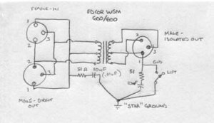
The splitter circuit is pretty simple. It’s developed from the Jensen application notes, more transformer design info can be found at their website.
The circuit is pretty simple. The only components required besides the transformers and connectors are a 51 ohm resistor and 10nF capacitor for a radio frequency network. I used polyester film caps and metal foil resistors for low noise. A ground lift switch is optional… it isn’t a bad idea because it allows for potential ground loops, but it does complicate the build a bit.

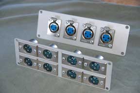
The front and back panels for the 4 channel splitter. There’s barely enough room for the connectors.
I first built a two-channel version, and I’m glad I did… I figured out where my screw-ups were. The case I selected was very tight… too tight for the two-channel version, really, so I was able to devise a better way to locate the components for the four-channel unit. When you build these, it’s best to wait to mount the transformers until after the connectors have been mounted and wired. And it’s difficult to machine the case sides for connectors or switches, you want to use only the smooth face plates for mounting hardware.
Wiring the unit was made easier by not bolting anything to the case before soldering… I made that mistake on my two-channel unit. And I saved a bunch of connectors by hard-wiring pigtails to the two-channel splitter, but it makes it cumbersome to store and vulnerable to damage. I decided to be conventional with the four-channel version and use connectors, but I’ll need to solder up eight short cables to go along with it. Soldering cables isn’t difficult, but rather time-consuming.

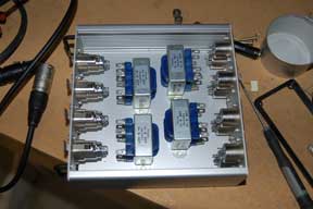
The case layout with the transformers in place. They’ll be bolted into position after they’re soldered.
I’ll be adding more info on this project as it develops.
Update: Well, my splitter has been completed for some time now. It works great. In use, it’s a bit heavy… not something I can put in my bag, but it’s normally used on the cart anyway. The size isn’t inconsequential, either, though this is certainly the smallest case that would fit the unit. As it was, I didn’t have room for ground lift switches. Soldering the leads was a bear, because I was trying to keep the leads as short as possible. I used a mini shielded cable that I bought from Trew Audio that is normally used in lavalier mics.

Could you tell me what modifications would be necessary to use one or two channels as line splitters? Such as for guitar or kybd.
Thanks for your comment. Bill Whitlock has written an excellent article for Jensen transformers about splitters. Take a look here, it should answer your questions far better than I could.
Best, BG
Pingback: BGilbertSound 2010 in review | Brian Gilbert Location Sound
Hi Brian,
I’m the owner of a recording studio in Italy, your project it’s very intresting… I will offer live recording service very soon and I want to try your schematic… where can I find it in a good resolution?
Thank You!!!
Enrico
Enrico: Where in Italy? We’ve been twice… mi piace molto andiami in Italia (sorry, my Italian is not at all what I’d like). If I had a way to make money there, I’d move in a heartbeat.
All you’ll ever want to know about transformer splitters is on the Jensen website… here’s the link. ciao, BG
Hello Brian, thanks for reply!
I found everything I need on Jensen website.
I live and work in Forlì, an unknown town near the Adriatic coast, very sad place… ha ha ha!!!! But I’m happy with my family and my littel boy, my son, he’s just one year old.
If you turn up again in Italy don’ forget to contact me!!! I will teach you Italian (?) and you will teach me how to keep the boom raised up for more that 10 minutes… he he he
best wishes
enrico
Enrico- It’s a deal… though I think teaching you to put a boompole in a C-stand holder 😉 is a lot easier than teaching me Italian. It will probably be several years before I return again… it’s expensive to travel… but I’m certain I will come back, maybe with my sailboat, then I could stay longer. I’m curious, though… why is Forli a very sad place? I looked at some snapshots of Forli on Google, and doesn’t look like a bad place at all. But I’m biased… generally, in Italy, the smaller the town, the better I like it (except Venice, I loved it there. Perhaps no cars are the key… I love small towns that you can’t drive through the center!)
Of course, if you looked at snapshots of Chattanooga, it seems at first like a wonderful town. And it is, unless you want to work in audio or video production… then it’s a real struggle. I often have to drive to Atlanta, Nashville, or Knoxvillle to work… (all three are larger, all are about 2-3 hrs drive away) Chattanooga is an affordable place to live, but there’s just not enough production going on here
Brian, you’re right… and I think that we mean the same problems about our towns…
In reality Forlì as become a dormitory suburb, no business venture, no money for culture and arts, just a fair place to walk sunday in center with family… Forlì has just a great position in history, from Roman Empire to second world war. But this fact I have idea that doesn’t intrest to the customers of my business… he he he!!!
Chattanooga for example has a fine river, I’ve seen in some photos (me too on Google, I’m a copycat), great pic-nic in summer!
I read on officially Chattanooga website that your city seems to be on of the 50 best places to live, this say tha National Geographic, NOOOOT BAAAAD!!!!!
But, a question… do you really have intention to sail through the atlantic ocean with your boat??? You are not a sound engineer, but a skilled sailorman smoking pipe, confess! I’ll wait you standing on the dock of Cesenatico!!!
I’d like to come in Tennesee, maybe with my family, by fly (no boat!). “…I’m goin’ to Graceland…” sang the great Paul Simon.
Enrico:
I’m both, actually… see the following links:
I doubt that, in reality, I’d ever be able to afford the time and cash to sail the Atlantic circle… it takes about 35 days to make it to Gibraltar. More of a dream than an actual plan. As long as we are making wishes, I’d love to buy a casetta near Umbria or the Levant and fix it up to retire there… I think. I’m sure the reality of living in Italy full-time is far different than I’ve experienced. But I do love the time I’ve spent there. Best, BG
I have absolutely to say you are a wellspring of learning Brian… I’m not jocking, I took a look at your books, very well done! You almos infect me the sail passion.
Please always remember: dreams can really come true. In 37 years of my life nothing happened… In just 1 year I become dad and I’ve built the recording studios of my dreams… he he…
Well, for this time you can come in Italy with plain, just to do a “reconnaissance mission”…
you are right, live here in Italy for Italians it’s so hard, especially with the actual tax regime. Consider that you gain 1000$ for a recording job and you catch in your pocket less than the half of this amount.
I hope to meet you in person one day…
ciao
Hi Brian,
I’d like to build a portable version of your project to connect 2 Audio-Technica ATR-3350 to an iphone 5 mic input. What suggestions do you have? Can I get away only with an Y splitter?
I’d try a plain Y-splitter. The transformer balanced mic splitter is an output device; in other words, it takes a single mic output and splits it to feed two inputs. You’re going the other way around… taking two outputs and feeding a single input. But I don’t know anything about an iPhone’s input impedance or level requirements, so I can’t say for sure. I don’t know what a 3350 is, either… if they are condenser mics, there’s a good chance it won’t work because of the power requirements. Sorry.
Hi, Brian
I’ve been looking for the transformer that you recommended, but the link is broken. I don’t understand anything about this device, so could you tell me which would be the possible substitution?
Thank you
Ricardo
From Manizales, Colombia
Ricardo: Do a google search for it… the Edcor site isn’t the clearest, but I was able to find the WSM 600/600 without too much trouble. Just in case, I replaced the link in the article. While there are other substitutes (Jensen makes some great transformers, for example, as do Cinemag and others), I like the Edcor transformers because they’re US- made, have good performance at a reasonable price point. Good luck!- BG
Hi Brian. Just found your site while doing research for XLR splitting. I think you have spelled out everything I am looking for. I am building a box for our band to start doing a separate monitor mix from FOH. I am looking to build a 20 input 40 output box. I will definitely do a small build first, that seems logical.
My question is, are you still happy with your build? Do you still like the WSM 600/600s? Do the transformers need to be mounted on the long side for heat dissipation? or would they work on the short side?
thanks.
/chris
Mic level signals are very low in terms of amps, so the xfmrs don’t get hot. They’re somewhat heavy so they need to be well secured.
The build has worked out great, though these are rarely used. I do prefer the one with the male and female panel mount connectors, as opposed to the one that I made with pigtails… easier to store.
Sorry to ask another question before getting my previous one answered… But what is the difference between a mic splitter and a line splitter? Is it just the Impedance? 150 vs 600
thanks again
/chris
Not sure that there is a difference… but I’m not familiar with a “line splitter.” Line level, you mean? That’d be odd, to split the signal after a preamp, unless it were some kind of long line driver. Over my pay grade, I’m sorry to say.
Is it just me or is the pictured schematic wrong? I’m no expert, but grounding the coil-tap seemed weird to me, and didn’t work when I tried it. I went and took a look at the Jensen schematics which seemed to confirm my suspicions:
Click to access an005.pdf
On another note, I really appreciate your putting up that link to the transformers. I just completed a small mic splitter as a test, but I’d like to build a full 16 channel splitter snake in the future. These transformers look like a very affordable, good quality option.
Also your article is really high in google’s search results and by far the easiest one to understand; if in fact I’m not mistaken about the schematic, it would be cool to get it fixed just for the sake of anyone else looking to build one of these. 😉
Hey there, I’ll be building a single rack unit version of this – is there a reason you omitted the 2.7K resistor across pins 2 and 3 across the isolated output? The Jensen document suggests having one there to help the overall frequency response of the system.
Thanks!
I’m making one of these so I can add outboard analog effects to one signal and the other runs dry. I bought 2 of the transformers ($13 each plus $16 priority shipping in a box that could easily hold 4.) My confusion is with the cap and resistor. “The only components required besides the transformers and connectors are a 51 ohm resistor and 10nF capacitor for a radio frequency network. I used polyester film caps and metal foil resistors for low noise. ” The resistor I found sales for $17 each or I buy a 1000 for who knows what. Might I be doing something wrong? The 10nF cap search takes me to 1.0nf caps. Is that the same thing? Anyway I could convince you to post a link? And if you took a photo of the finished product with the lid off, I’d love to see that too. Very few exist online of a passive point-to-point transformer splitter. Thank you, Mr. Gilbert
Wow, you’re right… I neglected to photo the completed split. I’ll have to look through some boxes to get a photo… I had to close the studio years ago when we moved, and now everything is buried in boxes somewhere. I’m not entirely sure where it is, may take awhile.
You’re definitely looking in the wrong place for resistors and caps. Get them from Mouser or Digi-Key… 51 ohm Vishay/Dale resistor, $4 for a hundred, 2% film:
https://www.mouser.com/ProductDetail/Vishay-Dale/CCF0751R0GKE36?qs=sGAEpiMZZMtG0KNrPCHnjXeT93wkI597xY0uBuLkupU%3D
Panasonic film caps, $3.98 for ten:
https://www.mouser.com/ProductDetail/Panasonic/ECW-FD2J103KQ?qs=sGAEpiMZZMv1cc3ydrPrF522MeGyoXxPPtkKZ%2FQ1Fj8Fi0N%2F9zn6Fg%3D%3D
Note- 10 NANOfarads is the same thing as .01 MICROfarads… it gets confusing and I have to make myself little notes about this sort of thing, since I don’t work with it every day. I have a lab notebook that’s filled with notes and circuits, in the style of Forest Mims old Radio Shack books. You can still get them for six bucks. Very approachable and recommended if you aren’t experienced.
Hope this helps
BG
Also, a sort-of warning… once you start using decent transformers in your signal chain, you’ll get addicted to them & you’ll want them on all your inputs. Your signal may sound better just by passing them through some iron. (but be sure to keep your connections short & twisted together.)
Splitting a signal for parallel processing is a good trick for these. You might be OK without the R-C filter & could skip it if you wanted. It’s a 300kHz filter for RF hash. Refer to the Jensen Application Note AN005… that’s where I got the info for my splitter:
Click to access an005.pdf
Ah ha! I confess, I’m totally schematic illiterate. However, I do seem to understand your schematic as a type of map. Thank you for the book recommendation. This project is activating my mind to be able to ask questions, which means I’ll retain more while researching. I did buy those caps and resistors, thanks for taking the time to post that. I was surprised to realize that in your schematic, the split is one “through output” and one transformer output. Is there any reason not to have more than one transformer output? I guess that could create a ground loop hum, maybe? Could the same cap and resistor dampen that hum? Or do I need one transformer for every transformer out? I see Radial Eng, uses a single Jensen JT MB DPC, but that could have more outputs than the transformer in your schematic. For the record, I’m already addicted to transformers. But I’ve been buying prebuilt Capi & JLM units instead of building my own. The mic splitter seems like the perfect place to start. I should have bought 4 or 8 so I could put as transformer in front of every input on my analog to digital audio interface! Thanks Mr.Gilbert, this was a great article. I’m surprised Capi doesn’t sell a DIY splitter project.
OK, your questions tell me that you have some research to do. Again, get that book… if you’re a beginner, it’s invaluable. It doesn’t explain everything there is to know about electronics, but it will give you a good start, and it’s the best that I’ve found, especially if you’re “schematic illiterate.” That statement tells me that you’re at a place where this book would be helpful. (I REALLY wish he had written an audio-centric version!). You can’t wire multiple outputs on the transformer for the same reason you can’t just skip the transformer altogether and use a bunch of Y chords… it’s the impedance load. Impedance is complex and I don’t fully understand it myself, but I know if you get it wrong it can cause a whole host of problems. CAPI is a fantastic company, you can’t go wrong with them. I’ve been buying from them for years and LOVE their stuff. I don’t know as much about JLM just because I haven’t tried them, but I’d expect them to be great as well. Good luck